Large injection-molded parts are difficult to fill consistently when several valve gates open at the same time. A sequential valve gate controller improves the process by controlling when individual gates open and close, allowing the melt front to advance through the cavity in a planned sequence.
For large or complex parts, this helps manufacturers improve filling balance, manage weld-line location, reduce unnecessary pressure variation, and achieve more consistent part quality. Research on sequential valve gate molding has also shown advantages in controlling injection and packing pressure as well as weld lines, particularly for large thin-wall parts.
As part size increases, the melt has farther to travel before the cavity is completely filled. Using several gates shortens the flow distance, but simply opening all gates together can create another problem: multiple melt fronts may meet in undesirable areas.
Sequential gating changes this filling pattern.
Instead of filling the cavity from every gate simultaneously, the controller activates each valve according to a programmed sequence. The next gate can open as the melt approaches its region, allowing the cavity to fill progressively rather than through several competing flow fronts.
This approach is particularly useful when a mold has:
long or uneven flow paths;
several valve gate locations;
areas where visible weld lines are unacceptable;
filling imbalance caused by complex part geometry.
Sequential valve gate technology is therefore widely suited to complex and large-part molding, where programmable gate sequence and timing provide greater control over cavity filling.
A weld line forms when separate melt fronts meet. With conventional simultaneous multi-gate filling, the position of that meeting point is largely determined by the mold geometry, gate positions, material behavior, and processing conditions.
A sequential valve gate controller gives the processor another adjustment point: gate timing.
By delaying a downstream valve until the primary melt front reaches the appropriate position, the new melt can join an already advancing flow rather than creating two independent fronts that collide directly. This makes it possible to relocate certain weld lines or reduce their visibility in critical areas.
The objective is not simply to open gates one after another. The timing must match actual cavity filling behavior.
Opening a gate too early can recreate competing flow fronts. Opening it too late may increase pressure requirements or disturb the surface around the gate. Mold-flow analysis and molding trials should therefore be used to establish the initial sequence, followed by fine adjustment under actual production conditions.
Studies of sequential valve gate molding have reported improved control over weld lines and reductions in defects such as air traps compared with conventional filling methods.
Both pneumatic and hydraulic actuators can be used with sequential valve gate systems. The better choice depends on the mold, valve pin requirements, available utilities, and the level of control required.
Pneumatic valve gate systems are commonly selected when a relatively simple and clean actuation system is preferred. They can be suitable for many general injection molding applications where the available air supply provides sufficient and repeatable valve movement.
Hydraulic valve gate systems are often considered when greater actuation force or more demanding valve pin movement is required. Hydraulic systems can also offer additional opportunities to manage valve pin movement in advanced large-part applications.
In either case, repeatable timing matters as much as the actuator type. The controller must reliably coordinate its sequence with the injection molding machine so that each gate responds at the required point in every cycle. Commercial sequential valve gate systems are therefore designed to work with both pneumatic and hydraulic hot runner configurations.
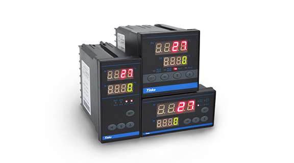
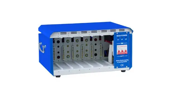
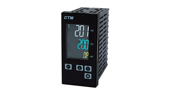
Tinko provides several controller configurations so molders can match the control system to the number of valve gates, installation requirements, and level of operator interaction.
For molds requiring an 8-gate wall-mounted controller, the D600 uses an LED interface, while the D800 provides an LCD touch-screen interface. Both are designed for pneumatic or hydraulic valve gates and allow individual gates to be controlled according to the required sequence.
For larger or more complex valve gate systems, the M20 Touch Screen Controller supports configurations up to 24 zones and provides individual valve control through a larger touch-screen interface. Tinko specifies both pneumatic and hydraulic valve compatibility for this series.
The M10 Portable Valve Gate Controller provides another option where a compact controller is preferred and supports up to 24 valve gate control zones. Tinko also offers modular and other controller formats for different mold arrangements.
Choosing the appropriate controller should therefore start with the mold layout and required valve sequence rather than controller size alone. The number of gates, actuator type, trigger signal, timing strategy, and future expansion requirements should all be considered before the control system is specified.
A sequential valve gate controller independently determines when individual valve gates open and close during the injection cycle. This allows the melt flow front to be managed more precisely instead of allowing every gate to fill the cavity simultaneously.
It can reduce certain weld lines or move them away from critical cosmetic or structural areas, but results depend on gate position, part geometry, material behavior, and the selected timing sequence. Sequential control should be combined with proper mold design and process optimization.
It is particularly valuable for large, long-flow, thin-wall, or geometrically complex parts that require several injection points. Research and commercial SVG applications both identify large and complex parts as important use cases for sequential gate control.
Start with the number of valve gates and whether the mold uses pneumatic or hydraulic actuation. Then evaluate the required timing resolution, machine trigger signals, control modes, installation format, and whether additional zones may be needed for future molds.
For large-part molding projects, Tinko can help match the sequential valve gate controller to the hot runner layout and valve control requirements so the system is configured around the actual molding process rather than a generic control setup.
 English
 français
 Deutsch
 Español
 italiano
 русский
 português
 العربية
 Türkçe
 dansk
dansk Svenska